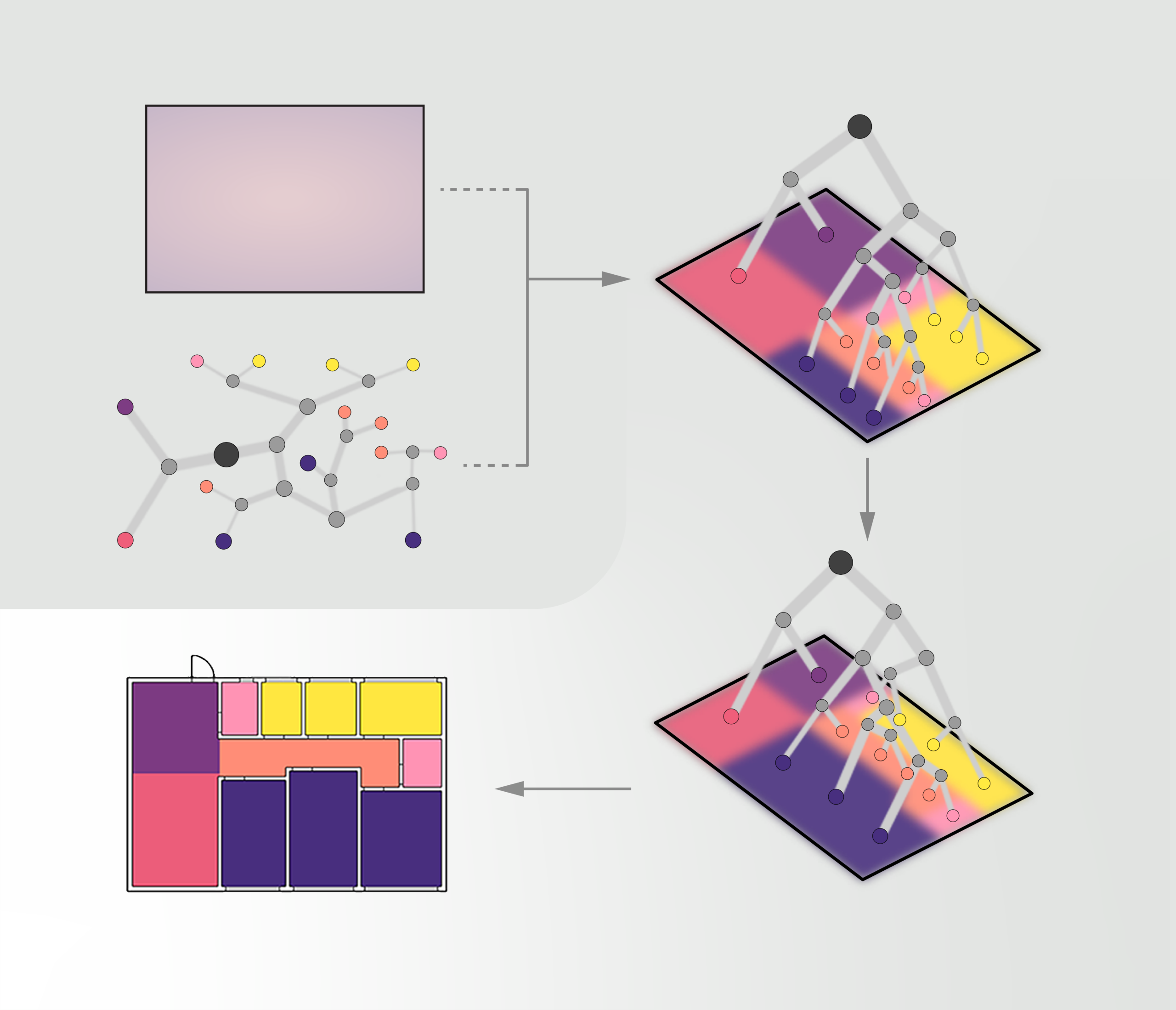
We present a gradient-based inverse-design workflow for controllable floorplan synthesis. A hypergraph couples spatial subdivisions with room-access relationships, while differentiable soft splits enable optimization toward target room areas and compactness. The workflow adapts reference plans to new boundaries and supports adding or removing rooms for interactive architectural design.
Shaoyi Wang, Ramon Elias Weber · Spatial Systems Lab, UC Berkeley · 2026
Cite — BibTeX
@article{WANG2027107322,
title = {Inverse design of architectural floorplans with gradient-based optimization of binary subdivision graphs},
journal = {Automation in Construction},
volume = {193},
pages = {107322},
year = {2027},
issn = {0926-5805},
doi = {https://doi.org/10.1016/j.autcon.2026.107322},
url = {https://www.sciencedirect.com/science/article/pii/S0926580526005637},
author = {Shaoyi Wang and Ramon Elias Weber},
keywords = {Inverse design, Floorplan generation, Binary subdivision graph, Hypergraph, Computer-aided design},
abstract = {Computer-aided floorplan synthesis automates a core task in architecture and construction planning: balancing room programs, connectivity, areas, and boundary constraints. The fuzzy nature of machine-learning models makes it difficult for generative methods to achieve the precision and predictable edits needed in architectural design. Building on a hypergraph representation coupling binary subdivision graphs with access graphs, this paper proposes a gradient-based inverse-design workflow for controllable floorplan synthesis. Its differentiable soft-split formulation converts subdivision parameters into continuous room masks, allowing room areas and compactness to be optimized while preserving a prescribed or retrieved subdivision structure. Compared with non-differentiable optimization, this method is faster and performs favorably on several connectivity metrics. Residential floorplan experiments show improved access satisfaction and area accuracy over existing methods. The effectiveness of the proposed method is demonstrated across several design scenarios, supporting interactive computer-aided design and controllable layout synthesis for early-stage decision making under varied design requirements.}
}
Generate a floor plan
Start with a boundary and room requirements, retrieve a compatible reference graph, and optimize the layout.
Adapt boundaries
Different reference graphs produce alternative layouts within the same boundary.
Edit rooms
Designers can add or remove rooms by editing the graph, then rerun optimization to adjust the surrounding spaces.
Hypergraph representation
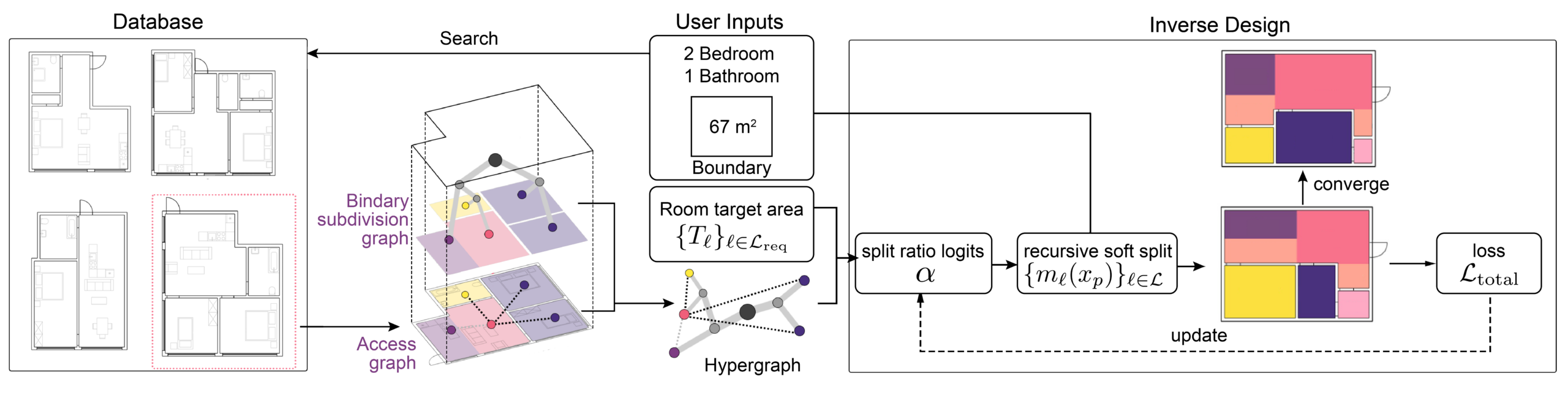
The hypergraph couples an access graph with a binary subdivision graph. The access graph captures room-to-room access using an adjacency matrix, while the binary subdivision graph encodes the hierarchical spatial partitioning of the floorplan. Given a target boundary and room program, the method first retrieves compatible hypergraphs from the database by comparing room counts, boundary shape, and boundary semantics.
Soft binary subdivision graph
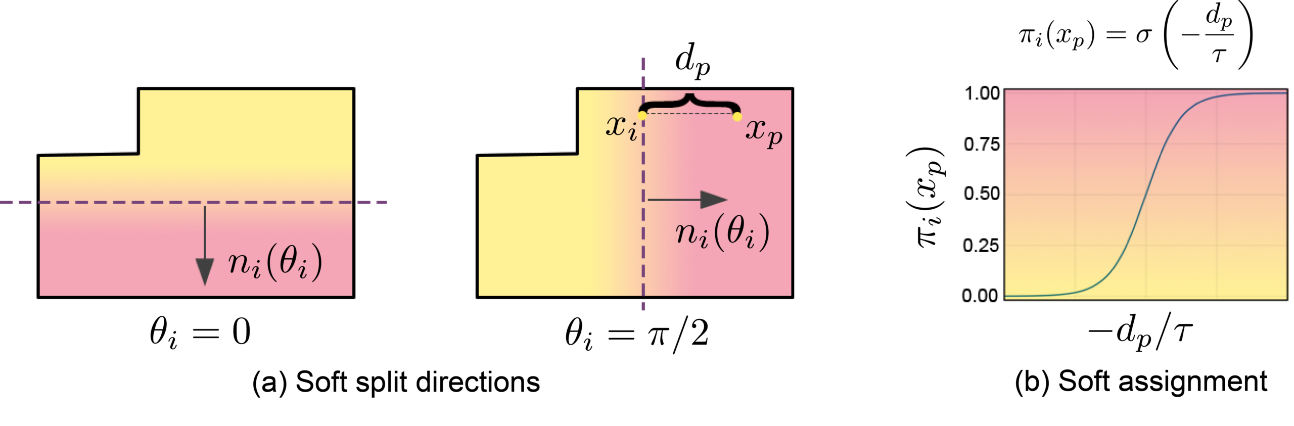
The proposed method models the floorplan layout structure with a binary subdivision graph defined over a fixed boundary polygon. The graph captures the hierarchical subdivision of the interior, where each node induces a soft partition. These soft partitions are evaluated on a regular grid, providing differentiable estimates of room areas and other layout objectives.
Recursive subdivision and differentiable floor plan
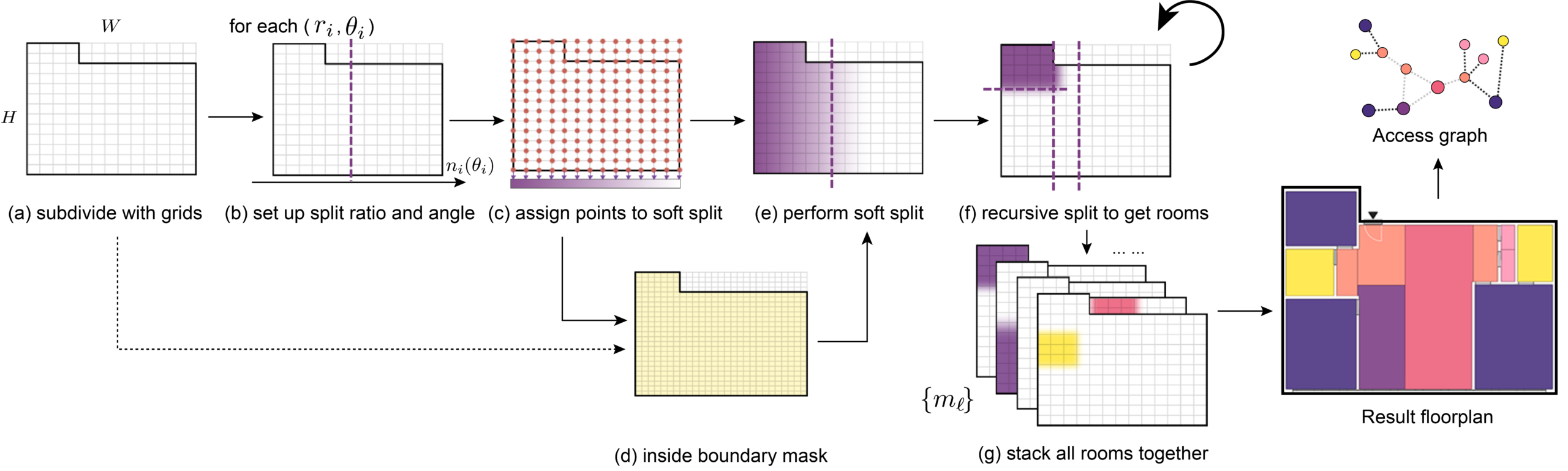
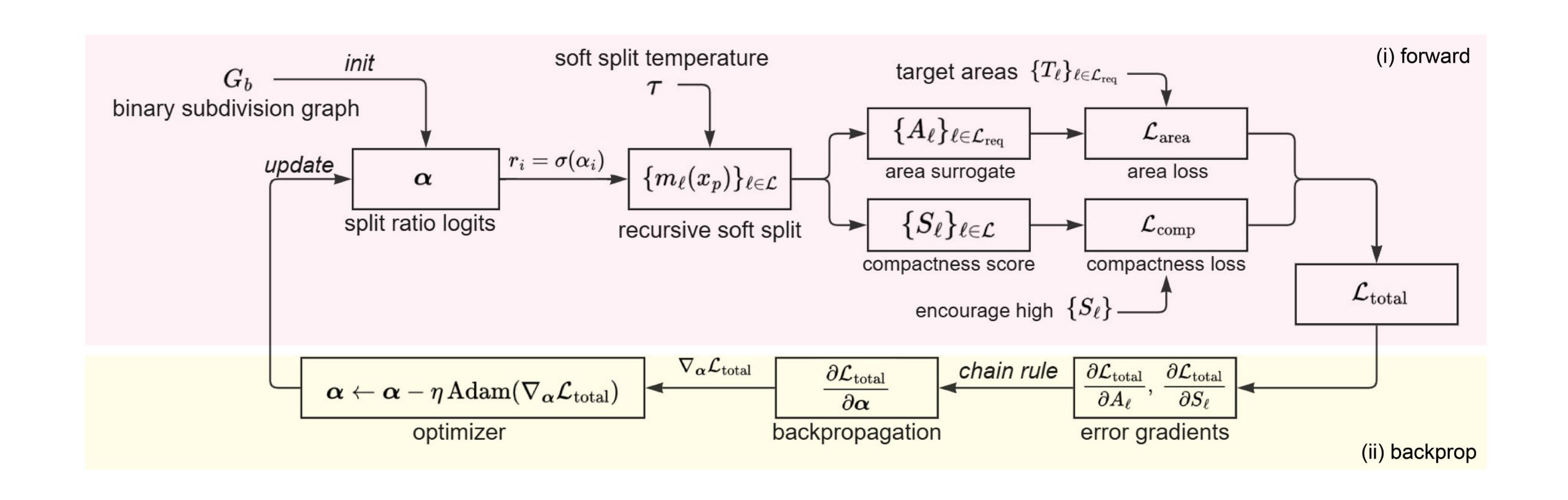
To turn this graph into geometry, the boundary polygon is discretized into a grid of sample points. At each internal node, a split angle and ratio define the cut. Smooth left/right assignments are multiplied with the parent mask to obtain the child masks.
Starting from the root node, the soft split rule is applied recursively until the traversal reaches the leaf room nodes. Stacking these soft room masks forms the floorplan. The collection of leaf masks defines a differentiable floorplan representation: room areas and shape measures vary smoothly with the split ratios, providing the forward model for inverse design.
How it works
Inverse design loop
The pipeline uses this differentiable layout engine as the forward model in an inverse design loop, optimizing the split ratios so that the resulting floorplan satisfies the target room areas within the given boundary. The inverse design loop alternates between a forward pass that evaluates the current layout and its objective, and a backward pass that backpropagates gradients to the split ratios.
Grasshopper walkthrough
Reference search, inverse design, and room editing in Rhino/Grasshopper. Watch on YouTube ↗